


Instrukcje obsługi i montażu
Tutaj znajdą Państwo aktualne instrukcje obsługi i montażu naszych produktów.
-
Assembly instructions for mooring compensator
Item number 814156
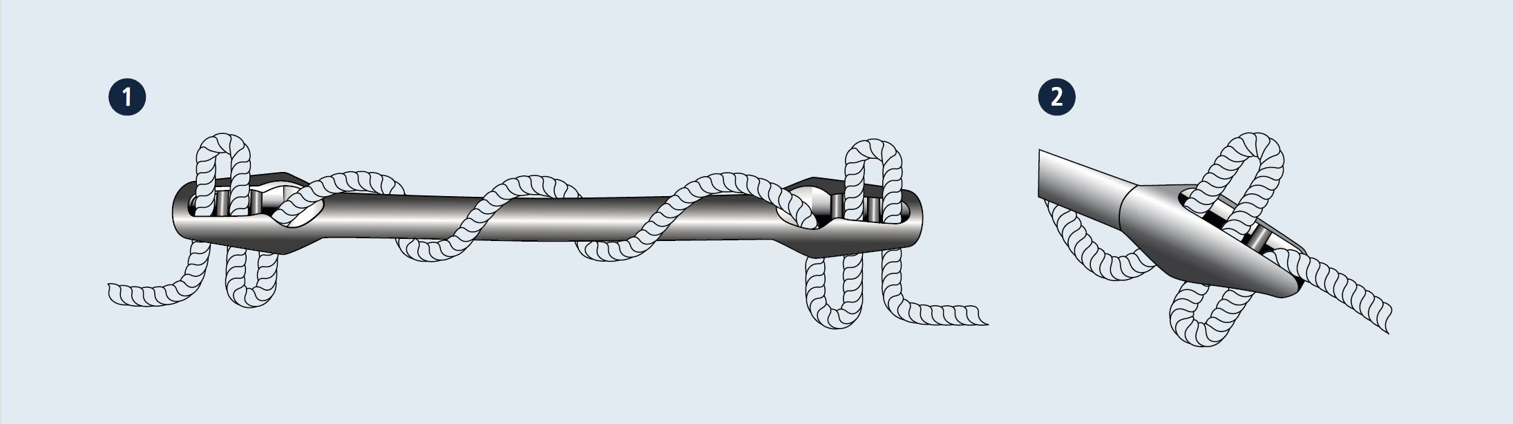
więcej informacjiFitting
- Thread the rope through the shock absorbing end.
- Then thread the rope through the other end.
- The length of the mooring compensator can be adjusted by the number of windings (two to four).
- On the underside of the mooring compensator the rope must fitted into the notch.
- You need approx. 200 - 300 mm rope for three windings.
- Position the mooring compensator properly and pull the rope taut.
Features
- Made of rubber (EPDM)
- For mooring lines for boats and yachts
- Absorbs shock from the swell at the jetty
- Easy fitting
- UV and saltwater-proof
- Low noise
-
Assembly instructions for Sprayhood rail holder
Item number 814637 + 814589
więcej informacjiFitting
Measure and mark the mounting points for the tube holders on the sprayhood-frame.
For better fixing please drill the tube of the sprayhood-frame with 3 mm diameter or countersink the tube. Assemble the adjusting ring on the tube, bring him in position and fix the socket set screw with a hex key.
Pin the socket set screw of the adjusting ring through the fabric of the sprayhood. Then apply the seal with the rubber side on the sprayhood fabric. We recommend to cutting the fabric hot with a soldering iron, so that it doesn‘t fray. Afterwards assemble the tube holder on the socket set screw.
Finally assemble the cover-screw in the thread of the tube holder, plug in the handrailtube in the tube holder and fix it with the socket set screw.
In the second tube holder the tube must be inserted in advance before the ring is adjusting into position and fixed with the socket set screw.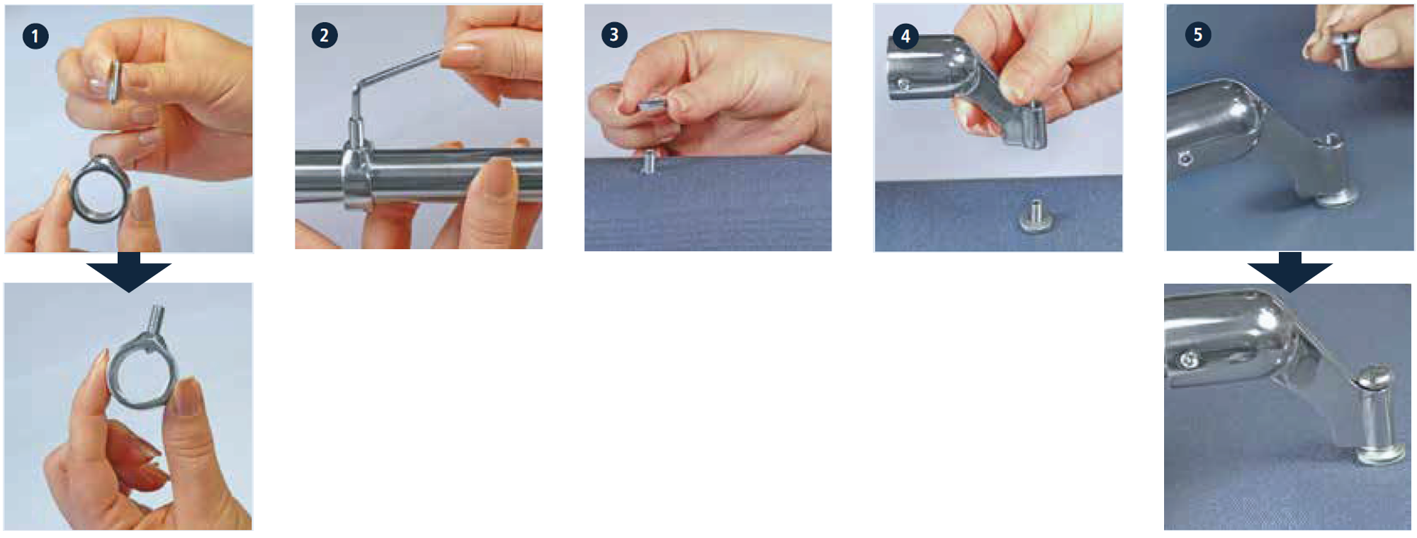
-
Assembly instructions for flat line spool
Item number 8551
więcej informacjiFitting
Put the washer on the thread of the flat line spool.
Insert the provided screw through the handle knob.
Install the handle knob with the washer on the flat line spool.
Hold the guide arm on the flat line spool to mount the axle.
Put the axle through the flat line spool. In this connection pay attention to the locking holes to set the correct angle of the guide arm.
Put the distance washer under the self-locking nut and tighten.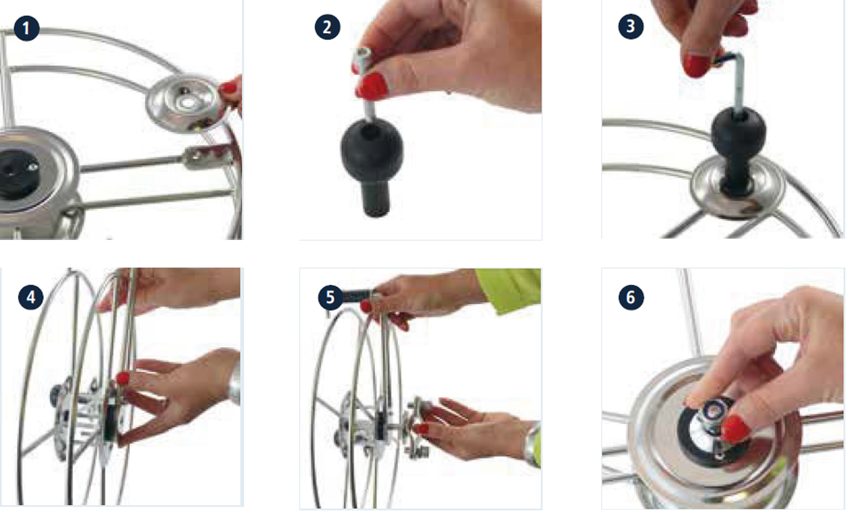
-
Instructions for quick attach terminals
Item number 8403, 8404, 8406, 8763
więcej informacjiFitting
Slide the cone onto the cable.
Slide the jaws onto cable leaving equal spacing between the jaws.
Place the brass washer on the cable end. The distance to the end of the cable must be 5 mm.
Turn the lock nut all the way back onto the terminal head.
Assemble the terminal by threading the cone strong onto the head.
Place sealant in the tip of the cone around the wire.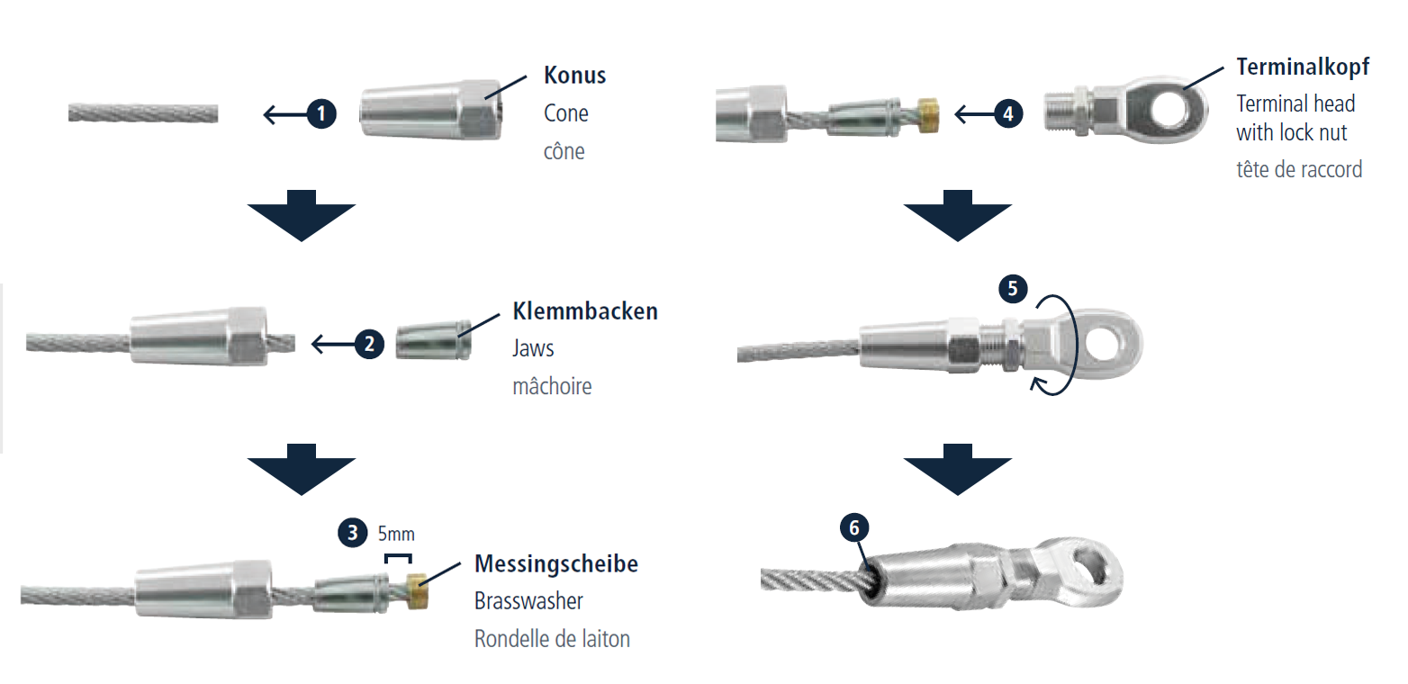
-
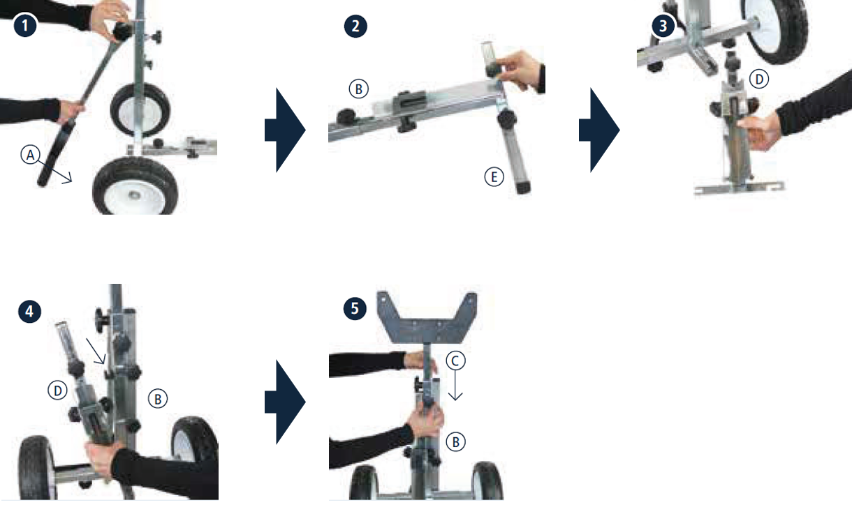
Assembly and stowage instructions for outboard trolley
Item number 814697
więcej informacjiFitting
Mount the handle A with the base frame B.
Plug the engine holder C in the base B frame and fix it.
Plug the guideway D in the base frame B and fix it.
Mount the foot E with the guideway D.
Plug the wheels F into the base frame B and fix them.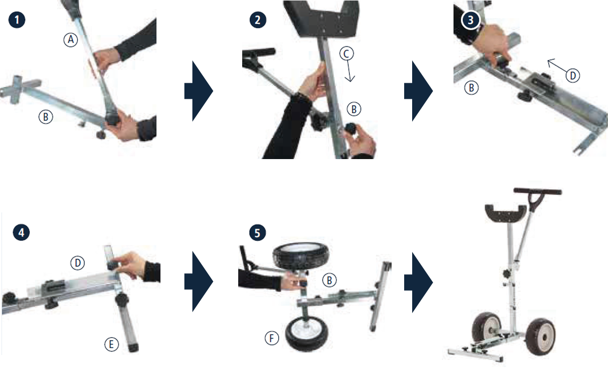
Stowage instructions
Loose the handle A and fold it down.
Loose the foot E and hang it into the eyes on the base frame B and fix it.
Loose the guideway D.
Hang the guideway D into the eye on the base frame B and fix it.
Loose the engine holder C and slide it in the guideway B.
-
Assembly instructions for wire rope clip sits
Item number 8248 + 815059
więcej informacji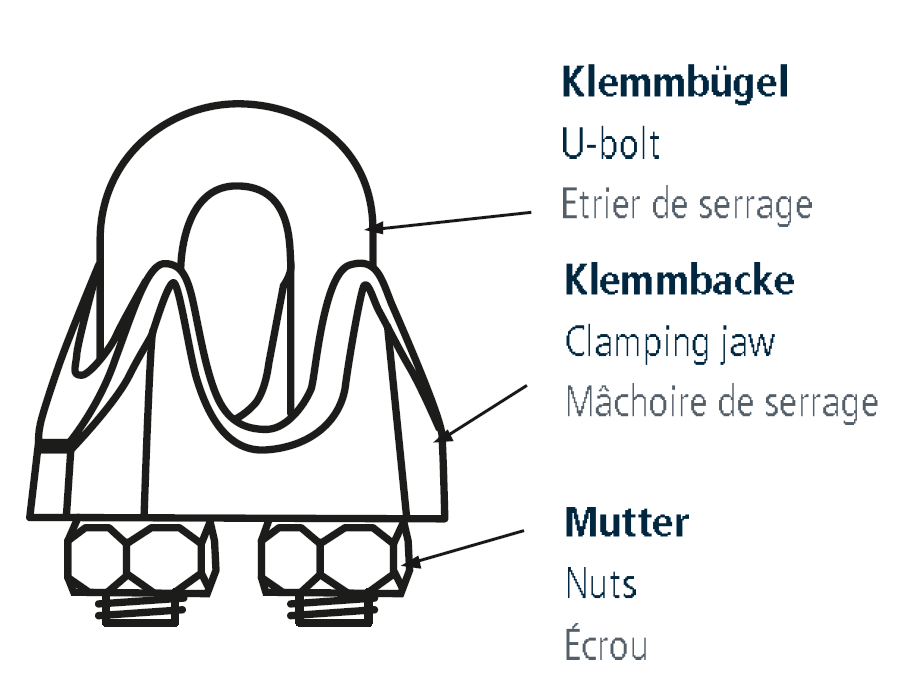
Wire rope clips (Art. 8248, 815059) are used for fixing loops, with or without insertion of a thimble
(Art. 8247, 8536, 8636, 815061, 815058) at wire rope ends.Flexible, bendable wire ropes of type 7 x 7 (Art. 8379, 815055, 8381, 814593), 7 x 19 (Art. 8382, 815056) or 6 x 36 (Art. 815082) should be used for this purpose.
Wire rope clips are an alternative to connections with ferrules or terminals as they can be quickly installed on site, but can also be loosened again. In addition wire rope clips are cheap.
Assembling
The clamping jaw
 rests relatively positively on the loaded rope strand
  . The U-bolt
  lies almost point-like on the unloaded rope end
  . The nuts
  should be tightened by hand at first so
that the wire rope clip can be moved into position. Then the nuts should be tightened alternately with an appropriate tool. The mounted wire rope clip transfers the force of the loaded rope strand to the less loaded rope end.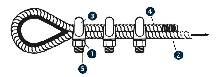
Formation and quantity
The first wire rope clip
sits close to the thimble . For loops without a thimble, the distance between the first wire rope clip to the bolt (or similar) should be three times the bolt diameter - but at least 15 times the rope diameter. The
distances between the following wire rope clips should be 1.5–3.0 x (= width of the clamp jaw). The end of the less loaded wire rope looks out behind the last wire rope clip approx. 10x the wire rope diameter. At least, minimum 100mm. In total, this results in an approximate foldover length of the wire rope. The recommended minimum number of wire rope clips depends on the rope diameter (see chart).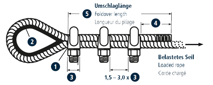
When using a larger number of rope clips, the foldover length must be increased proportionally. Coated wire ropes has to stripped of their coating in the entire contact area of the wire rope cliips before processing. Wire rope clips similar to the former DIN 741 should be used only for subordinate requirements. Please check the admissibility for your construction.
Nominal size* Minimum quantity Foldover length 2 3 ~ 170 mm 100 mm 3 3 ~ 180 mm 100 mm 4 3 ~ 190 mm 100 mm 5 3 ~ 200 mm 100 mm 6 3 ~ 220 mm 100 mm 8 4 ~ 270 mm 100 mm 10 4 ~ 300 mm 100 mm 12 4 ~ 370 mm 120 mm 13 4 ~ 380 mm 130 mm 16 4 ~ 450 mm 160 mm 18 4 ~ 510 mm 180 mm 22 5 ~ 660 mm 220 mm *Nominal size = max. wire rope diameter. Wire ropes with intermediate diameters must be fixed with the next larger wire rope clip.